


Introduction:
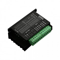
TB6600 arduino Stepper Motor Driver is an easy-to-use professional stepper motor driver, which could control a two-phase stepping motor. It is compatible with Arduino and other microcontrollers that can output a 5V digital pulse signal. TB6600 arduino stepper motor driver has a wide range power input, 9~42VDC power supply. And it is able to output 4A peak current, which is enough for the most of stepper motors.
The stepper driver supports speed and direction control. You can set its micro step and output current with 6 DIP switch. There are 7 kinds of micro steps (1, 2 / A, 2 / B, 4, 8, 16, 32) and 8 kinds of current control (0.5A, 1A, 1.5A, 2A, 2.5A, 2.8A, 3.0A, 3.5A) in all. And all signal terminals adopt high-speed optocoupler isolation, enhancing its anti-high-frequency interference ability.
As a professional device, it is able to drive 57, 42-type two-phase, four-phase, hybrid stepper motor.
Features:
Support 8 kinds of current control
Support 7 kinds of micro steps adjustable
The interface adopts high-speed optocoupler isolation
Automatic semi-flow to reduce heat
Large area heat sink
Anti-high-frequency interference ability
Input anti-reverse protection
Overheat, over current and short circuit protection
Specification:
Input Current:0~5A
Output Current:0.5~4.0A
Control Signal:3.3~24V
Power (MAX):160W
Micro Step:1, 2/A, 2/B, 4, 8, 16, 32
Temperature:-10~45℃
Humidity:No Condensation
Weight:0.2 kg
Dimension: 96 * 71 * 37 mm
Terminal Definition Description
Signal input
CP +: positive pulse signal input.
CP-: pulse signal input negative terminal.
DIR +: positive and negative motor control positive end.
DIR-: motor is positive, negative control negative end.
EN+: motor offline control is positive.
EN-: Motor offline control negative terminal.
Motor winding connection:
A+: Connect motor winding A + phase.
A-: Connect the motor winding A-phase.
B+: connect the motor winding B + phase.
B-: connecting the motor winding B-phase.
Operating voltage connection:
VCC: DC power supply positive (Note: 10V <VCC <42V).
GND: negative DC power supply.
Signal input optocoupler isolation connection
Input signal interface has two kinds of connection: the user can use common anode connection or common cathode connection.
1. Common anode connection: connect CP +, DIR + and EN + to the control system respectively. If the power supply is + 5V, it can be connected directly. If the power supply is greater than + 5V, an additional current limiting resistor R , To ensure that the internal optical drive to provide drive 8-15mA drive current. Pulse input signal through the CP-access; At this time, DIR-, EN- in the low-effective.
2. Common Cathode Connection: Connect CP-, DIR- and EN- to the ground of control system (SGND, isolated from power supply) respectively; + 5V pulse input signal is added through CP +; at this moment, DIR +, EN + High effective. The current-limiting resistor R is connected in the same way as the common-anode connection.
Note: EN terminal can not be connected, EN is valid when the motor rotor is free (offline), then you can manually rotate the motor shaft, do the adjustment for you. After the manual adjustment is completed, set EN to inactive to continue the automatic control.
TB6600
دیتاشیت
فـایل های ضمیمه (442.38k)